About Bandpass Filters
The use of bandpass filters is one of the simplest and most economical ways to transmit a well-defined band of light and to reject all other unwanted radiation. Their design is essentially a thin film Fabry-Perot interferometer formed by vacuum deposition, and consists of two reflecting stacks separated by an even-order spacer layer.
Because the Fabry-Perot filter is Lorentzian in shape, the cut-on and cut-off slopes are shallow and the rate of attenuation in the out-of-band blocking range is slow. To improve the slopes and increase the attenuation in the blocking band, we introduce more cavities into the construction of our standard dielectric bandpass filters.
Environmental Considerations
Ambient temperature and optical path geometry are important factors to consider in selecting or specifying bandpass filters.
Ambient Temperature
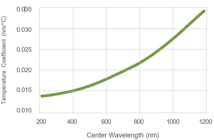
The center wavelength of a bandpass filter shifts linearly with changes in ambient temperature—up with a positive change and down with a negative change.
The temperature coefficient chart below gives a good approximation of the shift in wavelength for a given temperature change.
To counter these effects, Andover has developed Temperature Controllers that help to maintain the ambient temperature of bandpass filters. (For more information see page 68 (Temperature Controller).
Temperature Wavelength Shift Coefficient

Angle of Incidence
The central wavelength of the all-dielectric Fabry-Perot filter shifts lower with an increase in the incident angle. The amount of shift depends upon the incident angle and the filter’s effective index (N*). This feature can be very useful when tuning a filter to the desired central wavelength. Use the formula below to determine the wavelength shift of a filter in collimated light with incident angles up to 15°.

Where:
| λ θ | = | Peak wavelength at incident angle θ |
| λ 0 | = | Peak wavelength at normal incidence |
| n 0 | = | Refractive index of incident medium (air=1.0) |
| n * | = | Effective index of the filter assembly |
| θ | = | Angle of incidence |
When using a filter with non-collimated light, the wavelength shift will appear somewhat less than that of collimated light at the same angle. In a cone of light, only the central ray is normal to the surface while all others are increasingly off-angle. To approximate this shift, use this same formula and divide the results by two. (This approach works in systems where the full cone angle is up to 20°).
More Information
General Specifications
| Diameter Tolerance: | +0/-0.25mm | |
| Usable Aperture: | Filter Size | Usable Aperture |
| 12.5mm Ø | 9.0mm Ø | |
| 25.0mm Ø | 21.0mm Ø | |
| 50.0mm Ø | 45.0mm Ø | |
| Surface Quality: | 80-50 (Per MIL-PRF-13830B) | |
| Optical Quality: |
Commercial instrumentation grade (TWF 3-5 waves per inch Parallelism 3-5 arc/minute) |
|
| Out-of-Band Blocking: | 1 x 10⁻⁴ avg. from X-ray to FIR | |
| Specification Temperature: | +23ºC | |
| Max. Survival Temp Range: | CW/L 214-380nm | -50ºC to +50ºC |
| CW/L 380.1-2400nm | -50ºC to +70ºC | |
| Humidity Resistance: | Per MIL-C-48497A | |
| Mechanical: | Mounted in an anodized aluminum ring |
